Thursday, 3 January 2013

robot room


5. Flip-Flop 7474 Logic-Chip Brains

(article continued from previous page)
The Flip-Flop Robot drives forward until it hits an obstacle, and then reverses until it hits another obstacle. This back-and-forth process continues indefinitely. By limiting the functionality to this very rudimentary behavior, it can be generated from an off-the-shelf chip instead of requiring a fancy microcontroller. Thus, this is a good robot project for beginners.
An even simpler circuit with the same functionality can be found at the Back-And-Forth Robot.
Robot direction 74hc74 schematic.
Robot direction 74HC74 schematic.
Avid fans of Robot Room will recognize the 7474 chip from the Laser Control project. This chip has two independent one-bit memory cells. You can read all of the operational details and see a movie in that article.
Briefly, the 7474 has a set (pin 10) and a clear (pin 13). The rear bumper switches are connected to the clear pin. When the rear bumper is pressed, the chip’s output (pin 9) is cleared (0V). This output connects to the motor driver chip and makes the robot drive forward. The function of the 7474 is to remember the output state even after the bumper is released.
The front bumper switches are connected to the set pin. When the front bumper is pressed, the chip’s output (pin 9) is set (5V), rather than clear (0V). This commands the motor driver chip to drive the motor backwards. The 7474 remembers this new output.
An oddity of the 7474 chip is that the set and clear pins are activated by a low (GND 0V) signal. Therefore, resistors R4 and R5 provide a high (5V) signal by default, so that the chip will not normally think that the set or clear pins are being activated. The bumper switches connect the appropriate pin to 0V when pressed, to activate the set or clear feature.
The power switch (SW1) connects the circuit to the battery when turned on. The diode (D1) prevents electricity from flowing in the wrong direction if the batteries are inserted backwards. Current is only allowed to flow in the direction of the arrow on the diode symbol. Backwards batteries would otherwise destroy the chips.
Capacitors C2 and C3 provide a smooth, local power source as the battery voltage goes up and down with power consumption. This helps prevent the chip from resetting or randomizing due to random electrical noise.
Bonus: The laser project only needs the bottom half of the 7474 flip-flop chip, and this project only needs the top half. You can combine the circuits to make a robot that starts and stops with a laser pointer, and that goes forward and reverse based on bumpers. You'll need to substitute the motor driver on this page for the FAN8200 motor driver chip. Simply connect the laser output (pin 6) of the 7474 to the enable pin (2) on the FAN8200, and the direction output (pin 9) of the 7474 to the input pin (6) on the FAN8200.

Bumper Switches

As discussed earlier, the bumper switches connect the corresponding input pins on the 7474 to GND (0V) when pressed.
Schematic of the front and rear bumper snap-action switches.
Snap-action switches have a nice feature where they can activate when the switch is pressed (normally-open pin) or when not pressed (normally-closed pin). In this case, we only want the 7474 chip to receive 0V when a switch is pressed, so the 0V (GND) wire is soldered to normally-open and the signal wire is soldered to common.
Notice that the front bumper switches are wired together (both connect to GND and both connect to the 7474 input pin 10). It doesn’t matter which switch is pressed -- or even if both are pressed at the same time. In any case, the input pin gets connected to ground. The same goes for the rear bumper switches.

Single Motor Driver

The IXDN404 chip isn’t officially a motor driver chip. It’s actually a power MOSFET driver chip. However, it does an acceptable job supplying power to small motors.
Because this project only needs to drive a single motor, the 8-pin IXDN404 chip fits nicely in the small breadboard.
Simple single motor driver schematic with an IXDN404.
A similar setup is described on my H-bridge page. The IXDN404 is featured in Intermediate Robot Building. Both are good sources of information if you want more details. I usually place four diodes on the motor outputs, but that’s optional for a low-end project since MOSFETs have built-in body diodes.
Admittedly, a MOSFET driver chip is a borderline poor choice for the 4.5V-6V voltage level of this robot. MOSFETs perform better at higher voltages. This is not a criticism of the IXDN404 chip. The IXDN404 is wonderful -- I’m just using it in low-performance situation.
If you find that your motor isn’t turning, use fresh batteries to reach at least 6V. Alternatively, consider adding a higher voltage battery pack to supply power to this chip. (Continue to supply 4.5V-6V to the 74HC74 chip. Higher voltages will destroy it.)
Alternatively, use the FAN8200 chip instead. It runs well at lower voltages, but can’t operate above 7V.

Implementing the Flip-Flop Robot Circuit on a Solderless Breadboard

As always, to help you wire this circuit in the real world, here are the direction controller and motor driver circuits on an actual breadboard.
Flip-flop circuit on a solderless breadboard.

Trouble in Doggy Land

Despite well-thought out plans, robots have a way of not working when they should. Two major problems were encountered during this robot’s test drive:
  1. The original 74AC74 chip intermittently reset to forward motion.
  2. The robot drove in circles, rather than straight.
Never feel bad if your robot has problems initially. Every robot I have ever built starts out with a serious malfunction. Tweaking the robot is part of the process and you should plan for it.

Random Resets and Advanced Chip Technology

The first problem was the most time-consuming and frustrating. The robot drove forward, hit a bumper, started to drive backward, but suddenly reset to driving forward again even though the back bumper hadn’t been pressed. I was awake until 2AM trying the following:
  • Loose wire? Wiggled, pulled, and reinserted.
  • Wires too close to the motor? Rerouted all wires to the opposite side of the robot.
  • Bad bumper switches? Checked out fine with a multimeter.
  • Bad flip-flop chip? Swapped with a fresh chip.
  • Need more capacitors? Added a variety of sizes throughout the board.
  • Pull-up resistor values too high? Decreased R4 and R5 to 1k.
  • Weak batteries? Attached to a solid bench power supply.
  • Bad motor driver chip? Swapped with a different type of chip.
  • Electrical noise from motor driver? Used separate power supplies for motor driver and flip-flop chip.
  • Need diodes on motor driver output? Added four 1N5817 Schottky diodes in the classic arrangement.
  • Spiky motor? Hooked up the oscilloscope and was horrified!!
Adding capacitors across motor terminals to reduce electrical noise.
Adding capacitors across terminals and metal tape around the motor to reduce electrical noise.
The GM7 is an inexpensive gearmotor -- which is great. However, it puts out a LOT of electrical noise. I added a couple of capacitors to the motor terminals and observed a moderate reduction in noise, but the noise was still significant. I even tried surrounding the motor with aluminum metal tape, without any apparent benefit.
I disconnected the motor from the circuit board and replaced it with a simple bicolor LED and a 330-ohm resistor. When the robot "drives" forward, the LED lights up red. When the robot "drives" backward, the LED lights up green. The circuit and bumpers worked perfectly fine with this setup. Therefore, the motor is the cause of the 74AC74 chip reset.
Now for the kicker: I connected the motor directly to an independent battery pack. That is, it was no longer connected to the rest of the circuit or robot power supply. Even so, simply applying power to the motor was enough to radiate electrical interference and reset the 74AC74 chip. Wow!
I was at my wit’s end. I had used up my bag of tricks to reduce electrical noise, but simply having the powered motor nearby was enough to prevent the robot from operating correctly. I was almost ready to cover the circuit board in a metal shell to act as a Faraday cage.
Before I did that, I decided to swap the 74AC74 chip for a 74HC74 chip. It provides the same functionality, but it uses more power and has weaker outputs. Surprisingly, the 74HC74 was much more noise resistant and didn’t randomly reset. Simply by using a 74HC74 instead of a 74AC74, I was able to restore the circuit to the basic parts described in the schematics at the top of this page.
This should serve as an important lesson that the “low-power” benefits of modern chips may make them more vulnerable to stray electrical fields.

A Question of Balance

With the circuit functioning properly, I was finally able to set the robot on the floor to enjoy its full glory. Sadly, though, it turned in a wide circle rather than going straight.
At first, I thought the problem was caused by the thin metal container bottom bending at the motor mount, causing the wheel to be tilted on the ground. The tilt would result in a conic wheel rotation. The tilt could be corrected at the motor mount with a shim, much as was done with the switch brackets.
Fortunately, it turns out that the robot’s weight was simply unbalanced. By shifting the battery pack away from the side with the motor, the robot’s motion straightened out.
Shifting the battery pack too far causes the robot to turn in a circle in the opposite direction. It is valuable to learn that an even distribution of weight is critical to a robot, particularly if the robot only has one wheel.
By the way, it is worth mentioning that both the solderless breadboard and the battery pack are attached to the candy-container body with Velcro hook-and-loop fastener strips. If I had chosen permanent double-sided sticky tape or screws, I would have been unable to balance the robot’s weight with slight shifts of the battery pack.

Conclusion

Don’t let these few negative issues give you the wrong impression about the final performance of the robot. Like all robots, adjustments make the difference between success and disappointment.
Positives:
  • All of the machining can be done with a Dremel and a couple of attachments.
  • I’m really pleased with how well the bumpers detect collisions.
  • The single motor concept proved to be perfectly satisfactory.
  • The GM7, although noisy, had enough horsepower to move the entire robot by itself.
  • A state-remembering robot can be constructed without a microcontroller.
  • The brains (IXDN404PI and MM74HC74AN) only cost about $2.50 at DigiKey.
  • The entire robot probably costs less than $25 in total.
You should consider making this robot, if only for the experience of using a flip-flop chip to remember a state. If you don’t have a suitable candy tin, you can base the entire body structure on a flat piece of balsa wood.
For an even easier circuit, check out the Back-And-Forth Robot.

Spring 2008 issue of Robot Magazine.

Norris LabsRobots with a Mission
Home LinksAbout
Romey - A Free Range Robot, Part 1
For the full article please see the Spring 2008 issue of Robot Magazine.
Romey is a simple robot with a very complex mission. Using only four sensors Romey is designed to roam aimlessly around the house and simply put, not get into any trouble. Although this sounds like an easy task, in actuality this can be quite a hazardous operation for any robot.
Like many of my prior projects, Romey is built on the A4WD1 Rover from Lynxmotion. The A4WD1 is a versatile wheeled platform that comes equipped with four 5 inch RC tires each with its own 12 volt motor. For Romey, the A4WD1 was configured with two additional decks on top of the basic chassis. Control for the motors is provided by a Sabertooth SX10 Dual Channel motor controller. To simplify the overall design, Romey uses a Basic ATOM Pro 28-M for its main controller.  The Atom Pro is installed into a Lynxmotion Mini Atom Bot Board.
Romey uses both ultrasonic and infrared distance measuring sensors. By using both technologies we can compensate for each of their weaknesses. The primary navigation sensor is the Parallax Ping ultrasonic distance sensor. Proximity and cliff detection is performed by three Sharp GP2D12 IR distance sensors. Each of the three sensors is connected to the Bot Board’s analog to digital ports.
Romey uses a wireless color video camera from Smarthome (#76004). This camera can transmit a standard video composite signal directly to a television up to 300 feet. By using a built-in IR illuminator it can see up to 45 feet in total darkness.
The software is written in the Atom Pro’s BASIC language and is divided into three major modules called behaviors. They are the Navigation, Avoid, and Danger behaviors. A behavior is a software module that takes inputs from one or more sensors and then triggers an action through the motor system. Each behavior is written as a subroutine and called sequentially by the main program loop. Ideally we would like each behavior to run concurrently and access the motor drive through some arbitration system but this is a bit beyond the Basic Atom’s capability. Since the behaviors we are using are reasonably simple and execute quickly, calling each behavior sequentially is more than adequate.
In the next article we will Internet enable Romey. As mentioned, we will replace the video camera with a wireless webcam and build a web browser based interface. In addition we will add a couple of bumper sensors to provide complete sensor coverage.
A detailed schematic and all the source code can be downloaded from the links on the right or from http://www.botmag.com/issue10.
 
Romey
Resources

Monday, 31 December 2012

DoorBell circuit using UM 66 IC


DoorBell circuit using UM 66 IC

Doorbell Circuit

Description

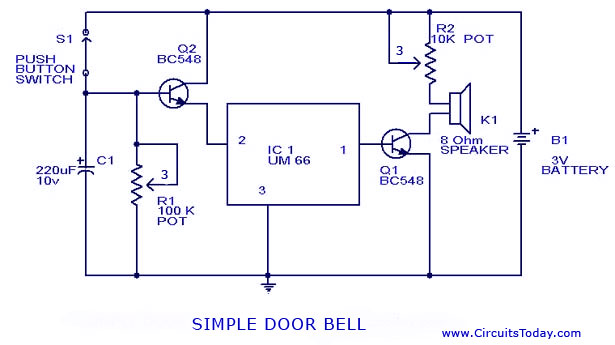
Here is a simple and easy to build doorbell circuit using IC UM 66.The  details of UM 66  is given in the older post Melody Generator using UM 66″. This is a slight modification of that circuit.In the previous circuit you have to keep the switch pressed for making the IC play the full music.Here if once the push button is pressed C1 is charged and the transistor Q2 will keep the IC playing the music till it ends.The time for the IC to play depends on discharging time of C1  which can be set by R1.Set R1 to select your time ,whether full tone or a part in one press.Transistor Q2 drives the speaker.

Doorbell Circuit Diagram with Parts List

Door bell circuit

Notes

  • Do not give more than 4.5 V to UM 66.
  • POT R2 is not necessary and can be bye passed .But if included you can set the loudness.
We have many other Tone Generator circuits that you may like take a look:
1. Tone Generator
2. High Power Siren Circuit
3. Melody Generator
4. Doorbell Circuit using 555 Timer
5. UJT Organ Circuit

Low cost / Automatic Emergency Light

Low cost / Automatic Emergency Light
author: Izhar Fareed - izhargmx.us - extremecircuits.net


Description

Here is a white-LED-based emergency light that offers the following advantages:

1. It is highly bright due to the use of white LEDs.
2. The light turns on automatically when mains supply fails, and turns off when mains power resumes.
3. It has its own battery charger. When the battery is fully charged, charging stops automatically.

The circuit comprises two sections: charger power supply and LED driver.The charger power supply section is
built around 3-terminal adjustable regulator (IC1) LM317, while the LED driver section is built around transistor BD140(T2). In the charger power supply section, input AC mains is stepped down by transformer to deliver 9V, 500mA to the bridge rectifier, which comprises diodes (IN4007x4). Filter capacitor (25v/1000uf)eliminates ripples. Unregulated DC voltage is fed to input pin 3 of IC1 and provides charging current through diode IN4007(D5) and limiting resistor (16ohm)R16. By adjusting preset 2.2K(VR1), the output voltage can be adjusted to deliver the required charging current. When the battery gets charged to 6.8V, zener diode conducts and charging current from regulator (IC1) finds a path through transistor BC547(T1) to ground and it stops charging of the battery. The LED driver section uses a total of twelve 10mm white LEDs. All the LEDs are connected in parallel with a 100-ohm resistor in series with each. The common-anode junction of all the twelve LEDs is connected to the collector of pnp transistor T2 and the emitter of transistor T2 is directly connected to the positive terminal of 6V battery. The unregulated DC voltage, produced at the cathode junction of Bridge(Diodes), is fed to the base of transistor T2 through a 1k resistor. When mains power is available, the base of transistor T2 remains high and T2 does not conduct. Thus LEDs are off. On the other hand, when mains fails, the base of transistor T2 becomes low and it conducts. This makes all the LEDs (LED1 through LED12) glow. The mains power supply, when available, charges the battery and keeps the LEDs off as transistor T2 remains cut-off. During mains failure, the charging section stops working and the battery supply makes the LEDs glow. Assemble the circuit on a general-purpose PCB and enclose in a cabinet with enough space for battery and switches. Mount the LEDs on the cabinet such that they light up the room. A hole in the cabinet should be drilled to connect 230V AC input for the primary of the transformer. I have tested the circuit with twelve 10mm white LEDs.You can use more LEDs provided the total current consumption does not exceed 1.5A. Driver transistor T2 can deliver up to 1.5A with proper heat-sink arrangement.

 
Download


low-cost-water-pump-controller-circuit.

Here the circuit diagram of low cost water pump controller. The automatic pump controller minimizes the need for any manual switching of water pumps installed for the functionality of pumping water from a reservoir to an overhead tank . It instantly switches on the pump once the water level within the tank falls below a specific low level (L), provided the water level in the reservoir is above a specific level (R). Subsequently, because the water level in the tank increases to an upper level (M), the pump is turned off instantly. The pump is turned on again only if the water level once again falls beneath level L in the tank, provided the level inside the reservoir is above R. This automated action
continues.


The circuit is intended to ‘overlook’ the transient oscillations of the water level that would otherwise trigger the logic to modify its state rapidly and unnecessarily. The circuit works by using a single CMOS chip (CD4001) for logic processing.
No utilization of any moving electromechanical elements within the water-level sensor has been made. This assures fast reaction, no wear and tear, and no mechanical problems. The circuit diagram can be seen on above image. The unit performed satisfactorily on a test run in conjunction with a 0.5 HP motor and pump.
The sensors applied to the circuit could be any two conducting probes, preferably resistant to electrolytic corrosion. For example, in the easiest case, a appropriately sealed audio jack could be utilized to operate as the sensor.
Low Cost Water Pump Controller circuit
The circuit may also be utilized like a constant fluid level maintainer. For this objective, the probes M and L are brought pretty near to one another to make sure that the fluid level is maintained within the M and L levels.
The benefit of this system is that it could be applied to tanks/reservoirs of any volume whatsoever. Even so, the circuit can’t be applied for purely non-conducting fluids. For non-conducting fluids, some modifications have to be prepared in the fluidlevel sensors. The circuit can on the other hand be kept intact.

Low cost Mic Mixer


Low cost Mic Mixer

Description
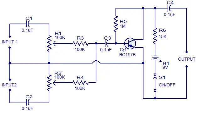
This is the schematics of a low cost mic mixer that can be assembled from the components in your junk box.This two channel mike mixer is designed for handling high impedance dynamic microphones.Transistor Q1 can be any general purpose pnp transistor like BC177 or BC157B. Resistor R5 biases the transistor while R3 and R4 provides channel isolation. How ever better the transistor quality better the performance.  C1 and C2 performs the job of input coupling and DC isolation while C4 is the output DC decoupling capacitor.Resistors R1 and R2 can be used for the level control of input signals.
Circuit Diagram With Parts List.
low cost mic mixer circuit
Notes
  • All capacitors are of ceramic type.
  • Always use a battery two reduce noise .
  • Avoid using power transistors for Q1. This is because power transistors have high leakage current and it adds to the noise which is not suitable for our purpose here

Low cost AM radio


Low cost AM radio

Description.
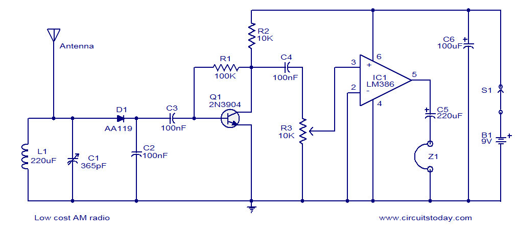
Here is the circuit diagram of a simple and low cost AM radio. The working of this radio circuit is straight forward. Inductor L1 and capacitor C1 forms the necessary tank circuit. Diode D1 performs the job of de-modulation. Transistor T1 is wired as a preamplifier whose output is further amplified by the IC LM386 to drive the head phone Z1. The 10K POT R3 can be used as a volume controller.
Circuit diagram.
low cost am radio
Notes.
  • The circuit can be powered from a 9V PP3 battery.
  • Use a 100cm long metal wire as antenna.
  • Experiment with the value of L1 for catching other bands.
  • The circuit can be assembled on a Vero board.